|
Moving |

|

|

|
|
Moving |
|
|
|
|
The movement of an object includes, in the most general case, both the translation of its reference point as well as its three-dimensional rotation around its reference point. For ease of handling, this most general form of movement has been broken up into a series of graphic movement patterns. |
... the box must remain unchecked in all of the dialog boxes described here!
A movement command can either be accessed with the context menu, the Selection menu or a keyboard shortcut. The descriptions in this chapter generally refer to the appropriate item in the Selection menu or the context menu. |
Moving an object means the translation of its reference point without rotation. After marking the object (or objects) the command Selection > Move… opens the Move dialog box. In this dialog box you can enter the new Cartesian coordinates of the reference point (the common reference point)
. In both cases it is possible to enter polar coordinates (length, angle) in place of Cartesian coordinates.
|
The rotation of an object basically means a rotation around its reference point in the plane of the main plate without the translation of its reference point. The rotate dialog box however also allows you to additionally shift the rotation or reference point. After marking the object (or objects) the command Selection > Rotate... opens the Rotate dialog box. In this dialog box you can enter the rotation angle in degrees. If you additionally edit the Cartesian or polar coordinates, you overlay the rotation of the object with a shift of its reference point (see above). |
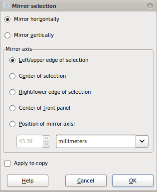
The mirroring of an object (or multiple objects) is performed in "Front Panel Designer" as "axis mirroring". After marking the object (or objects) the command Selection > Mirror… opens the Mirror dialog box. In this dialog box, you first choose between the vertical or the horizontal mirror axis. Then you determine the position of the mirror axis in relation to
|
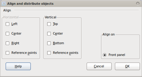
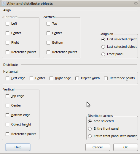
The alignment of a single object is a special case. It is performed with the command Selection > Aligning/Distributing… or Shift + a which moves an object in a horizontal and/or vertical direction relative to one or two edges or one or both center lines of the main plate. (The options "first ..." or "last selected object" are not relevant here.) The object can be aligned both with its contour (left/center/right and top/middle/bottom) as well as its reference point on the main plate.
|
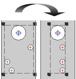
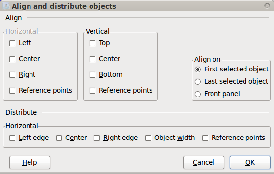
If multiple objects are to be aligned to an existing object, you have to mark them so that the reference object is selected as either the first or the last object. Then using the command Selection > Aligning/Distributing… or Shift + a either the contours or the reference points of the objects refer to the reference object. The example below shows how the outer contours of the small drilled holes "horizontal" and "right" were aligned to the large hole (in the center of the main plate):
As another option, objects can be aligned both through their outlines as well as their reference points to the four edges or the two center lines of the main plate.
Note: The lower part of the dialog box which determines the distribution of the objects has been cut out here. |
The distribution of multiple objects basically means their movement horizontally and/or vertically, either to achieve equidistant intervals between the X or Y coordinates of the reference points of the objects or equidistant intervals between their contours ("object width"), of which three cases can be distinguished as follows:
You can distribute selected objects both horizontally and vertically. For the horizontal distribution of selected objects please use the following options:
For the vertical distribution of selected objects please use the following options:
Note: The upper part of the dialog box which determines the alignment of the objects has been cut out here. |
You can use the command Selection > Aligning/Distributing… in particular either to align arbitrarily distributed objects on the same horizontal or vertical line, or to distribute them at certain equidistant intervals horizontally or vertically. |
After selecting one or more objects, the command Selection > Align on grid moves all of the selected objects with their reference points to the respectively closest grid point. |