Basic shape, dimensions etc.

  Previous topic Next topic JavaScript is required for the print function  

The geometry of the main plate is of essential importance for the design process as the dimensioning of the objects is primarily oriented to its edges and corners. That is why the main plate with its final dimensions should be available from the start, so that objects may be correctly placed, moved, copied and duplicated.

Basic shapes

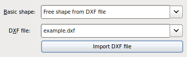
A selection can be made between the following basic shapes, with the thickness chosen from the entries in the list box:

The dimensions refer to the width and height of the rectangular main plate.

With an elliptical basic shape, the main and co-vertices are determined by the width and height of the elliptical main plate. If width and height are identical, then the main and co-vertices coincide as the diameters of a circle.

With this option, you first select the desired DXF file in order for it to be imported. For the exact requirements for the DXF file and tips on how to create it, see the chapter "Outline as free contour".

The displayed but non-editable dimensions relate to the width and height of the rectangular outline of the main plate with a free contour.

Please note, it is also possible to import the entire DXF file in one action: Create a new file from a DXF file

Although the main plate contour can be freely designed with a DXF file, it is possible to additionally customize the contour of the main plate by positioning one or more milling objects.

Please make sure that none of the objects protrudes more than 3 mm over the geometric edge of the main plate, otherwise the production process will be affected.

Dimensions

If necessary take the minimum and maximum values for width and height of the material from the respective table for the material ("Minimal and maximal processing area").

The thickness of the material is set by selecting a value from the corresponding list box.

A description of what may need to be considered when making subsequent changes to the geometrical dimensions can be found at the end of this chapter.

Corner radii

With the corner radii you can determine the outer radii of the 4 corners of a basic rectangular shape. If the box "Identical values" is checked, the values you enter in the input field for corner radius 1 also apply for the other 3 corner radii.

In-fill engravings

The "In-fill engravings" box is checked by default, meaning that all of your inserted engravings will be in-filled with your chosen colour. If you uncheck this box, then your front panel will be shipped with bright engravings.

In order to deliberately leave individual engravings bright, select "No in-fill colour" as in-fill colour in the properties dialog box for the object.

Remarks for production

Please take the opportunity to enter remarks for the production department, for example, if objects are to be manufactured, which cannot be inserted by default.

Subsequent change of height and width

The situation may arise however, that although nothing needs to be changed in the arrangement of the objects, the size of the main plate must be adjusted. The following "iron rule" must be observed here:

The height and width of the main plate – irrespective of the location of the origin – is always calculated from the lower left corner.

From this the rules are derived how the upper or right edge of the main plate can be moved resulting in an increase or decrease in the height or width of the main plate, without the existing objects now being moved in relation to the bottom or left edge of the main plate:

Change

right edge moves ...

upper edge moves ...

Increase

… outward

… upward

Decrease

… inward

… downward

Rules for changing the height and width of the main plate

All strategies for customizing the main plate geometry must therefore take these relationships into account:

Desired change

Outward

Inward

Move right edge by A

Increases width by A

Reduces width by A

Symmetrically move right and left edges each by A

Increases width by 2A;

select all objects, group and move group by DX = A.

Reduces width by 2A;

select all objects, group and move group by DX = -A.

Move left edge by A

Increases width by A;

select all objects, group and move group by DX =-A/2.

Reduces width by A;

select all objects, group and move group by DX =A/2.

Procedure for changing the main plate geometry

Subsequent increase in thickness to more than 4 mm

If there is a subsequent change in the material thickness to more than 4 mm, restrictions of the tool set for the objects already placed may result. In this case a differentiation can be made between thefollowing two situations:

Automatic adjustment of the tools is possible: In order to increase the thickness of the material to the desired size, the tools assigned to several objects will need to be adapted. Please choose between 'OK' for automatic adjustment or 'Cancel' in the dialog box which opens. You can open a list of the changes at the same time. If you permit the automatic adjustment, the desired material thickness is accepted and a message list displayed, so that you can control the changes that were made automatically.
Changes in the properties are required first: In order to increase the thickness of the material to the desired size, certain properties must be adjusted for several objects – a task which cannot be performed automatically. You can open a list of the necessary adjustments at the same time. Please confirm the opening message with 'OK'. A message list is displayed, so that you can control the changes that have to be undertaken manually. In addition, you will be shown which objects require the automatic adjustment of the tools.

With the aid of the message list, you can either trace the adjustments that have been made automatically, or inform yourself as to which of the current properties of which objects are incompatible with the desired change in thickness, so that a solution can be found if necessary.

Please note that automatic adjustments cannot be reversed by pressing Ctrl + z !

When the material thickness is changed, the available tool set also changes in the background. Depending on whether you want to reduce or increase the thickness of the material, the consequences are different:

The selection of a reduced material thickness is always accepted. In the course of this you can check whether new tools are perhaps available for certain objects (for example, for smaller inner radii).
The selection of a greater material thickness always results in the program checking in the background the consequences that would arise from a restriction of the tool set for the objects already placed. These can be divided into three cases:
1.The desired increase can be accepted without further ado.
2.The desired increase can be accepted following the automatic adjustment of the tools which are assigned to the placed objects.
3.The desired increase may only be adopted following the adjustment of specific properties for certain objects by the user.

In the 1st case, the new material thickness selected is directly accepted on exiting the main plate properties dialog box when you press the OK button, without you noticing the background check.

In the 2nd case, a dialog box appears for you to choose whether the program should make the necessary adjustments automatically or whether you would like to cancel the operation. If you decide on automatic adjustment, a corresponding message list is displayed.

In the 3rd case, a message appears that informs you of the necessary adjustments which must be made by the user. After confirming the message a message list is displayed, with the aid of which you can work your way through the necessary changes.