|
Row of drilled holes |

|

|

|
|
Row of drilled holes |
|
|
|
|
With a row of drilled holes - for example for buttons or LEDs - it is very easy to demonstrate the creation of a group of identical objects, by first creating a single object with the desired properties on the main plate, and then reproducing it as often as required at certain fixed distances apart. |
As in our case the coordinates of the row of drilled holes will be based on the upper left corner of the main plate, we will revert to the simplest method of moving the origin between the corner points of the main plate. To do this, please click on the "set origin" icon:
An icon bar appears to allow you to select between various methods of determining the origin on the main plate. Please select the icon "Enter coordinates based on snap point":
Now move the cursor over the main plate. This is then "snapped" at a total of 9 points on the main plate (recognizable by the appearance of a blue square). Please select the "top left" corner as the new origin for the main plate (click the left mouse button when the desired corner is "snapped").
|
To create the "mother hole" for the desired row of drilled holes, please select the icon "Insert drilled hole" or click Insert > Drilled hole from the toolbar:
An icon bar appears, you can choose between different methods of positioning the reference point of the drilled hole (= the center of the hole). Please select the icon "Manual coordinate entry".
|
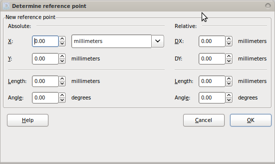
The dialog box "Determine reference point" now appears:
In this dialog box, please set the absolute X and Y coordinates to the following values:
Now press the button "OK". |
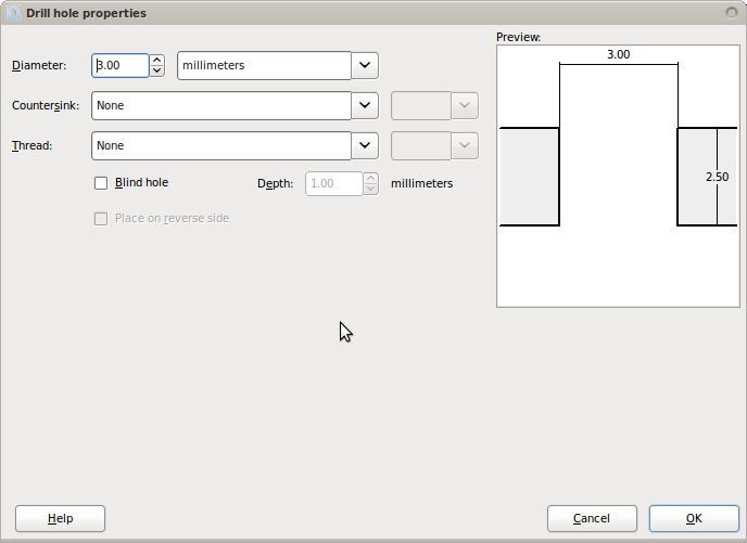
The dialog box "Drilled hole properties" now appears:
Set the diameter to the following value in this dialog box:
Now press the button "OK". |
Please mark the drilled hole you have created by clicking on the hole or drawing a frame around it.
Then click Selection > Move… to open the dialog box "Move selected objects". Check the box "Apply to copy" and then set the relative DX and DY coordinates to the following values:
Now press the button "OK". A second drilled hole now appears on the main plate below the first drilled hole - a deliberately generated "clone" of the "mother hole"! |
If you then click Edit > Repeat: Move to repeat the last action (moving the copy of an object), a third hole is generated with the same characteristics and in the same raster. The desired action can also be performed with the keyboard shortcut Ctrl + r . Please repeat the process until a row of drilled holes consisting of 8 objects has been created.
|
|
|